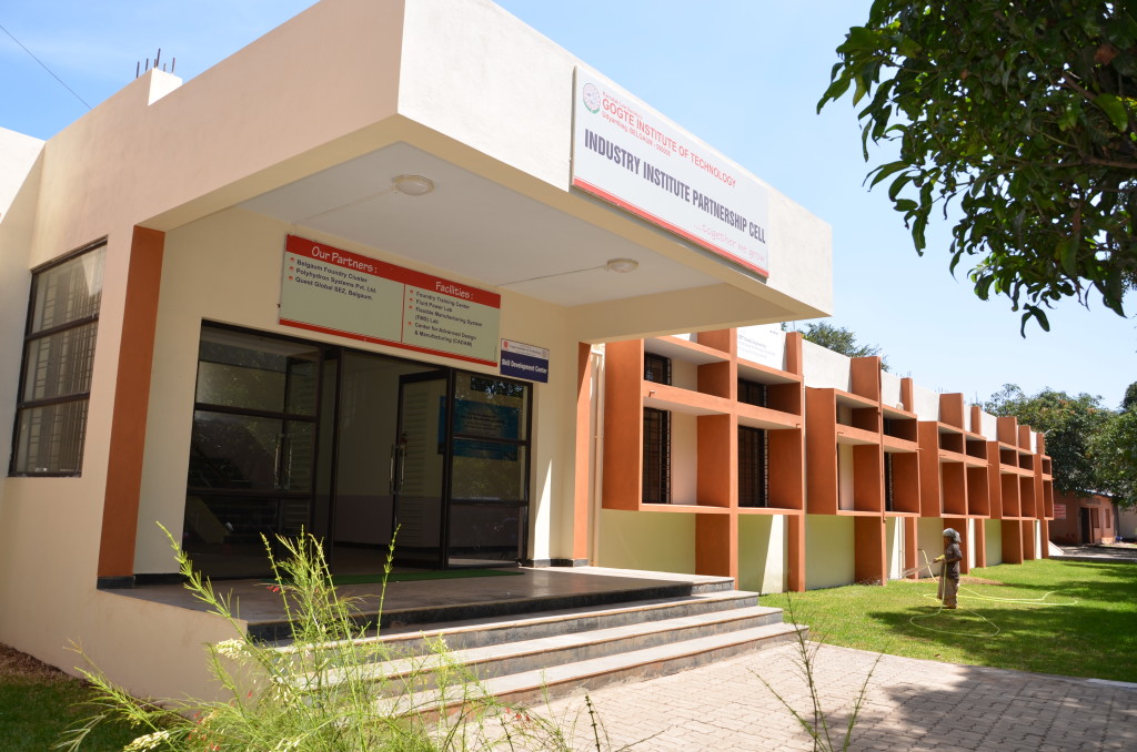
- Acts as liaison between Industry and the Institute.
- Organizes training programmes on advanced manufacturing techniques, CAD/CAM/Casting software and technical topics.
- Aids in the conduct of research work in various areas by providing facilities in the form of machines, software’s and computing facilities.
- Aids in the conduct of project work for UG/PG students in various areas.
It includes the following facilities:
- A Flexible Manufacturing System consisting of an XLMILL, XLTURN, AGV, AS/RS, Loading/Unloading Arms and a Central FMS controller.
- A Reverse Engineering Lab consisting of a Coordinate Measuring Machine (CMM) and A Rapid Prototyping (FDM) machine
- CADAM software training centre consisting of software’s like Autocast, Pro-e, UG-NX etc.
- Fluid Power Lab consisting of Hydraulic circuits trainer kits.
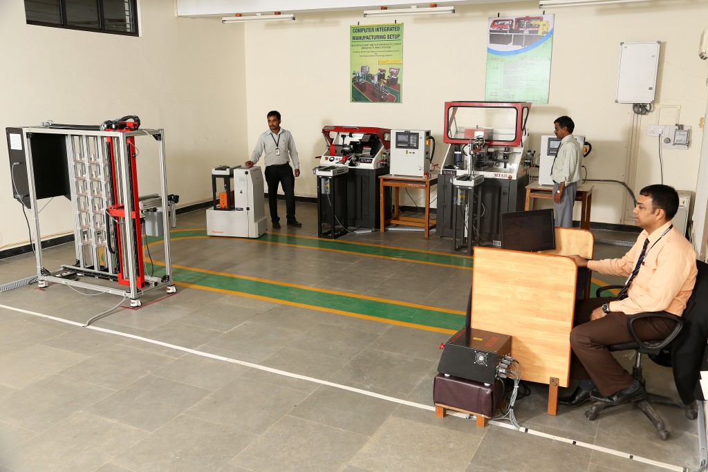
FLEXIBLE MANUFACTURING SYSTEM (FMS) is a production system consisting of a set of identical and/or complementary numerically controlled machine which are connected through an automated transportation system. Each process in FMS is controlled by a dedicated computer (FMS cell computer).
- The work machines which are often automated CNC machines
- Connected by a material handling system to optimize parts flow and
- A central control computer which controls material movements and machine f
Flexible Manufacturing System established in GIT at IIPC consists of the following equipments:
- XLTURN
- XLMILL
- AS/RS
- AGV
- CENTRAL FMS CONTROL COMPUTER
XLTURN is a two axes slant bed lathe machine with “MTAB CONTROLLER”. XLTURN can performs drilling, reaming, pocketing, grooving, parting, roughing and chamfering of circular and rectangular work pieces, using CNC programming and operating. The XLTURN is specifically designed for Education and Training, and is manufactured in accordance to the industrial standards. XLMILL is a three axes CNC bench-milling machine with “MTAB CONTROLLER”. XLMILL performs drilling, reaming, pocketing, roughing and chamfering the rectangular work pieces, using MTAB controller. The XLMILL is specifically designed for Education and Training, and is manufactured in accordance to the industrial standards. ASRS (Automatic Storage & Retrieval System) consists of one or more storage aisles that are serviced by storage retrieval (S/R) machine. (The S/R machines are sometimes referred to as cranes). The aisles have storage racks for holding the storage materials. The S/R machines are used to deliver materials to the storage racks and to retrieve materials from racks. Each AS/RS aisles have one or more input/output stations where materials are delivered into the storage system or moved out of the system. The input/output stations are called pick-and-deposit (P&D) station in AS/RS terminology. P&D station can be manually operated or interfaced to some form of automated handling system such as a conveyor or an AGVS. AGV (Automatic Guided Vehicle) is a material handling mobile system that follows wires in the floor. It is a microcontroller based system designed to be compatible with FMS/CIM integration. The AGV transports the raw material from ASRS (Automatic 2Storage and Retrieval System) to the Manufacturing machines and return the finished jobs from the machines, back to the ASRS. Aims of FMS
- To reduce costs
- Better utilization of the production equipment reduction of stocks (ex: Work in progress—capital shorter through put times)
- Reduction of piece part unit costs.
- To increase Technical Performance:
- Increased production levels
- Greater product mixture
- Simultaneous product mixture manufacturing
- Integration of the production system into the factory’s logistical system
- Smaller batch sizes
- Shorter or zero change over or reset of times
- Shorter lead times/delivery times
- Determination of production capacities
- To assist future Corporate Security:
- Increased Competitiveness and Quality
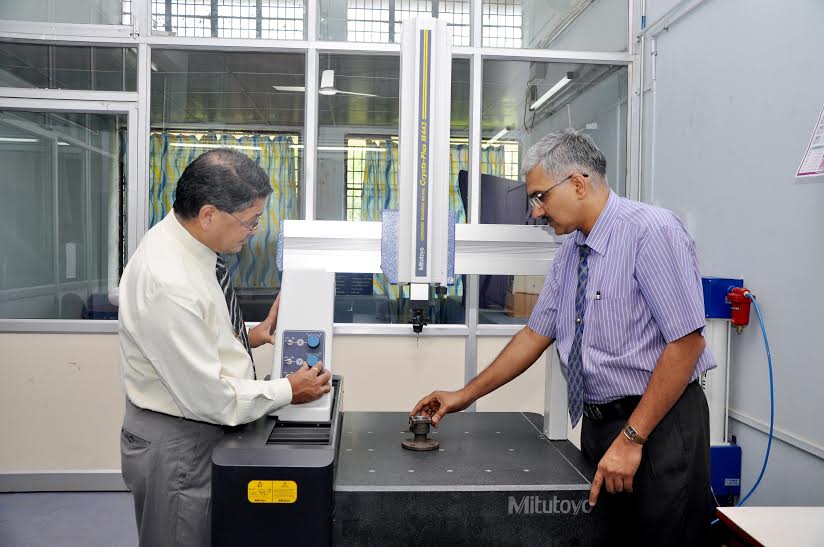
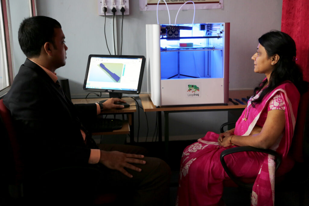
REVERSE ENGINEERING SETUP In some situations, there may be a physical part/ product without any technical details, such as drawings, bills-of-material, or without engineering data. The process of duplicating an existing part, subassembly or product, without drawings, documentation, or a computer model is known as reverse engineering. Reverse engineering is also defined as the process of obtaining a geometric CAD model from 3-D points acquired by scanning/ digitizing existing parts/products. The Reverse Engineering stetup at GIT consists of:
- Coordinate Measuring Machine
- Rapid Prototyping (Fused Deposition Modelling) machine
A Coordinate Measuring Machine (CMM) is a device for measuring the physical geometrical characteristics of an object. This machine may be manually controlled by an operator or it may be computer controlled. Measurements are defined by a probe attached to the third moving axis of this machine.. A machine which takes readings in six degrees of freedom and displays these readings in mathematical form is known as a CMM. Rapid Prototyping machine uses Fused Deposition Modeling (FDM), an additive manufacturing technique commonly used in the Rapid Prototyping (RP) industry to make parts. It is basically an additive process that layers the material together inorder to produce the finished prototype. A plastic coil is unwound through a heated nozzle, melting the material in the desired shape. One material is for support, while the other is for the 3D model itself. A 3D CAD file defines a calculated path for melted thermoplastics (print material) to travel and the model is built up, layer-by-layer, which is eventually cooled into a solid. In this process different materials can be used to create custom finishes, effects, product specifications and appearance. This Leapfrog machine incorporates an FDM system which includes two nozzles, one for part material and other for support material. The support material is relatively weaker is strength and can be broken easily once the complete part is deposited and is removed from substrate. CADAM (CENTERS FOR ADVANCED DESIGN AND MANUFACTURING) TRAINING CENTER The CADAM program is a student mentoring program conceived with the idea of strengthening the foundation of the principles of engineering and ensuring that students learn practical requirements of the industry today and get a perspective on future technology and engineering trends. CADAM has been set up in collaboration with Quest Gobal to develop a high quality pool of employable talent among graduating engineers by ‘forward integrating’ them with its future work force. This is enabled by:
- In-campus training of about 140 hours (3 months) for Final Year and pre-Final year engineering students for a batch size not exceeding 20
- Advanced syllabus and content designed for direct application to industry
- Training infrastructure and facility by institute
- Residential trainer, syllabus, training methods and evaluation by QuEST
- Employability to core industry by shortening lead time to be job-ready
- Issuance of a joint completion certificate
FLUID POWER LAB Provides an insight into the principles of hydraulics and pneumatics. It helps the students to understand the important hydraulic and pneumatic components and their functions in the simple systems. Also, it intends to provide the students the knowledge about various hydraulic power generating devices and how to transmit and control it. In addition students will be able to draw and construct the hydraulic and pneumatic circuits to perform certain functions. Fluid power systems easily produce linear motion using hydraulic or pneumatic cylinders, whereas electrical and mechanical methods usually must use a mechanical device to convert rotational motion to linear. Fluid power systems generally can transmit equivalent power within a much smaller space than mechanical or electrical drives can, especially when extremely high force or torque is required. Fluid power systems also offer simple and effective control of direction, speed, force, and torque using simple control valves. Fluid power systems often do not require electrical power, which eliminates the risk of electrical shock, sparks, fire, and explosions.